Feather RP2040 CAN Bus via U2IF by Adafruit
This board uses the U2IF firmware to communicate with Blinka and is run on the attached system via USB. See the Installation Instructions for more info.
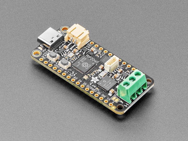
If you’d like quickly get started with CAN bus interfacing, with no soldering required, our Adafruit RP2040 CAN Bus Feather comes ready-to-rock with a microcontroller, CAN chipset and terminal blocks for instant gratification. The controller used is the MCP26525 (aka a MCP2515 with built-in transciever), an extremely popular and well-supported chipset that has drivers in Arduino and CircuitPython and only requires an SPI port and two pins for chip-select and IRQ. Use it to send and receive messages in either standard or extended format at up to 1 Mbps.
Feather is the development board specification from Adafruit, and like its namesake, it is thin, light, and lets you fly! We designed Feather to be a new standard for portable microcontroller cores. We have other boards in the Feather family, check’em out here.
CAN Bus is a small-scale networking standard, originally designed for cars and, yes, busses, but is now used for many robotics or sensor networks that need better range and addressing than I2C and don’t have the pins or computational ability to talk on Ethernet. CAN is 2 wire differential, which means it’s good for long distances and noisy environments.
Messages are sent at about 1Mbps rate - you set the frequency for the bus and then all ‘joiners’ must match it, and have an address before the packet so that each node can listen in to messages just for it. New nodes can be attached easily because they just need to connect to the two data lines anywhere in the shared net. Each CAN device sends messages whenever it wants, and thanks to some clever data encoding, can detect if there’s a message collision and retransmit later.
We’ve added a few nice extras to this Feather to make it useful in many common CAN scenarios:
- 5V charge-pump voltage generator, so even though you are running 3.3V on a Feather board, it will generate a nice clean 5V as required by the interal transceiver.
- 3.5mm soldered terminal block quick access to the High and Low data lines as well as a ground pin, without any soldering.
- 120-ohm termination resistor on board, you can remove the termination easily by cutting the jumper marked TERM on the top of the board.
- CAN control CS, Reset, Int, standby pins connected internally so you can use any FeatherWing without pin conflicts.
At the Feather’s heart is an RP2040 chip, clocked at 133 MHz and at 3.3V logic, the same one used in the Raspberry Pi Pico. This chip has a whopping 8 MB of onboard QSPI FLASH and 264K of RAM! There’s even room left over for a STEMMA QT connector for plug-and-play of I2C devices.
To make it easy to use for portable projects, we added a connector for any of our 3.7V Lithium polymer batteries and built-in battery charging. You don’t need a battery, it will run just fine straight from the USB Type C connector. But, if you do have a battery, you can take it on the go, then plug in the USB to recharge. The Feather will automatically switch over to USB power when it’s available.
Here’re some handy specs! You get:
- Measures 2.0” x 0.9” x 0.28” (50.8mm x 22.8mm x 7mm) without headers soldered in
- Light as a (large?) feather - 6.3 grams
- RP2040 32-bit Cortex M0+ dual core running at ~133 MHz @ 3.3V logic and power
- 264 KB RAM
- 8 MB SPI FLASH chip for storing files, images and CircuitPython/MicroPython code storage. No EEPROM
- Tons of GPIO! 21 x GPIO pins with following capabilities:
- Four 12-bit ADCs (one more than Pico)
- Two I2C, Two SPI, and two UART peripherals, we label one for the ‘main’ interface in standard Feather locations
- 16 x PWM outputs - for servos, LEDs, etc
- Built-in 200mA+ lipoly charger with charging status indicator LED
- Pin #13 red LED for general purpose blinking
- RGB NeoPixel for full-color indication.
- On-board STEMMA QT connector that lets you quickly connect any Qwiic, STEMMA QT or Grove I2C devices with no soldering!
- Both Reset button and Bootloader select button for quick restarts (no unplugging-replugging to relaunch code)
- USB Type C connector lets you access built-in ROM USB bootloader and serial port debugging
- 3.3V regulator with 500mA peak current output and power enable pin
- 4 mounting holes
- 12 MHz crystal for perfect timing.
- Support circuitry for CAN Bus using SPI interface
Purchase
Contribute
Have some info to add for this board? Edit the source for this page here.
Adafruit Blinka Installation
We use a special library called adafruit_blinka (named after Blinka, the CircuitPython mascot) to provide the layer that translates the CircuitPython hardware API to whatever library the Linux board provides.
For example, on Raspberry Pi we use the python RPi.GPIO library. For any I2C interfacing we'll use ioctl messages to the /dev/i2c device. For SPI we'll use the spidev python library, etc. These details don't matter so much because they all happen underneath the adafruit_blinka layer.
Features: Feather-Compatible, STEMMA QT/QWIIC, OSHWA Certified
Board Usage Options: Attached Device