Feather RP2040 RFM69 via U2IF by Adafruit
This board uses the U2IF firmware to communicate with Blinka and is run on the attached system via USB. See the Installation Instructions for more info.
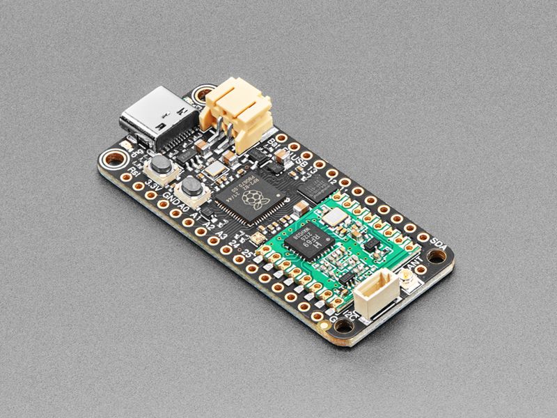
This is the Adafruit Feather RP2040 RFM69. We call these RadioFruits, our take on a microcontroller with packet radio transceiver with built-in USB and battery charging. It’s an Adafruit Feather RP2040 with a radio module cooked in! Great for making wireless networks that are more flexible than Bluetooth LE and without the high power requirements of WiFi.
Feather is the development board specification from Adafruit, and like its namesake, it is thin, light, and lets you fly! We designed Feather to be a new standard for portable microcontroller cores. We have other boards in the Feather family, check’em out here.
It’s kinda like we took our RP2040 Feather and an RFM69 breakout board and glued them together. You get all the pins for use on the Feather, the LiPoly battery support, USB C power / data, onboard NeoPixel, 8MB of FLASH for storing code and files, and then with the 8 unused pins, we wired up all the DIO pins on the RFM module. There’s even room left over for a STEMMA QT connector and a uFL connector for connecting larger antennas.
At the Feather’s heart is an RP2040 chip, clocked at 133 MHz and at 3.3V logic, the same one used in the Raspberry Pi Pico. This chip has a whopping 8MB of onboard QSPI FLASH and 264K of RAM! This makes it great for making wireless sensor nodes that can send to each other without a lot of software configuration.
To make it easy to use for portable projects, we added a connector for any of our 3.7V Lithium polymer batteries and built-in battery charging. You don’t need a battery, it will run just fine straight from the USB Type C connector. But, if you do have a battery, you can take it on the go, then plug in the USB to recharge. The Feather will automatically switch over to USB power when it’s available.
Technical Details
- Measures approximately 2.0” x 0.9” x 0.28” (50.8mm x 22.8mm x 7mm) without headers soldered in
- Light as a (large?) feather - approximately 6 grams
- RP2040 32-bit Cortex M0+ dual core running at ~133 MHz @ 3.3V logic and power
- 264 KB RAM
- 8 MB SPI FLASH chip for storing files and CircuitPython/MicroPython code storage. No EEPROM
- Tons of GPIO! 21 x GPIO pins with following capabilities:
- Four 12-bit ADCs (one more than Pico)
- Two I2C, Two SPI, and two UART peripherals, we label one for the ‘main’ interface in standard Feather locations
- 16 x PWM outputs - for servos, LEDs, etc
- Built-in 200mA+ lipoly charger with charging status indicator LED
- Pin #13 red LED for general purpose blinking
- RGB NeoPixel for full-color indication.
- On-board STEMMA QT connector that lets you quickly connect any Qwiic, STEMMA QT or Grove I2C devices with no soldering!
- Both Reset button and Bootloader select button for quick restarts (no unplugging-replugging to relaunch code)
- USB Type C connector lets you access built-in ROM USB bootloader and serial port debugging
- 3.3V Power/enable pin
- 4 mounting holes
- 12 MHz crystal for perfect timing.
- 3.3V regulator with 500mA peak current output
- SX1231 based module with SPI interface
- +13 to +20 dBm up to 100 mW Power Output Capability (power output selectable in software)
- 50mA (+13 dBm) to 150mA (+20dBm) current draw for transmissions, ~30mA during active radio listening.
- Range of approx. 500 meters, depending on obstructions, frequency, antenna and power output
- Create multipoint networks with individual node addresses
- Encrypted packet engine with AES-128
- Packet radio with ready-to-go Arduino & CircuitPython libraries
- Uses the license-free ISM band: “European ISM” @ 868MHz or “American ISM” @ 915MHz
- Simple wire antenna can be soldered into a solder pad, there’s also a uFL connector that can be used with uFL-to-SMA adapters for attaching bigger antennas.
Tutorials
- Guide is coming soon!
Purchase
Contribute
Have some info to add for this board? Edit the source for this page here.
Adafruit Blinka Installation
We use a special library called adafruit_blinka (named after Blinka, the CircuitPython mascot) to provide the layer that translates the CircuitPython hardware API to whatever library the Linux board provides.
For example, on Raspberry Pi we use the python RPi.GPIO library. For any I2C interfacing we'll use ioctl messages to the /dev/i2c device. For SPI we'll use the spidev python library, etc. These details don't matter so much because they all happen underneath the adafruit_blinka layer.
Features: Feather-Compatible, STEMMA QT/QWIIC, OSHWA Certified
Board Usage Options: Attached Device