Adafruit KB2040 via U2IF by Adafruit
This board uses the U2IF firmware to communicate with Blinka and is run on the attached system via USB. See the Installation Instructions for more info.
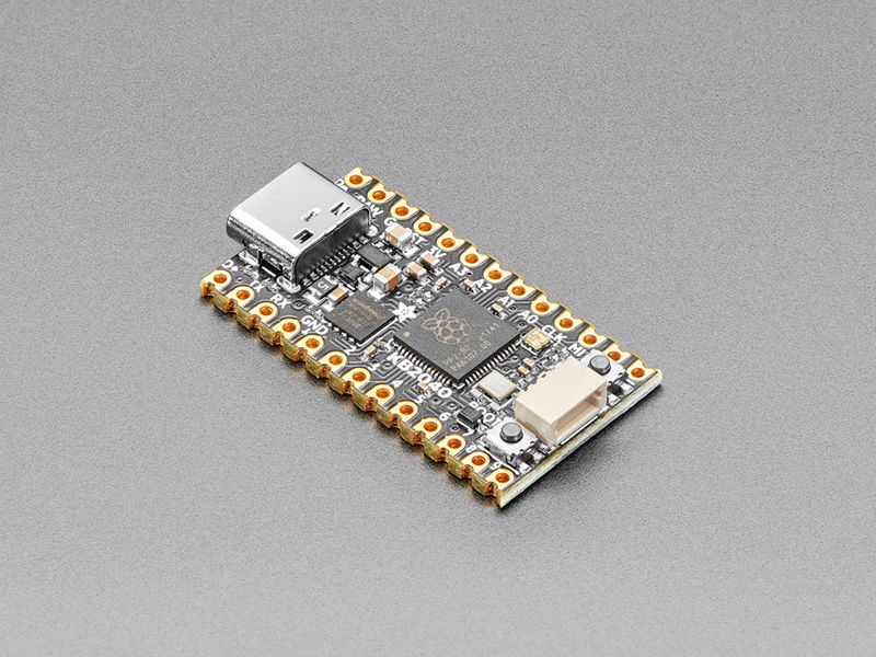
A wild Kee Boar appears! It’s a shiny KB2040! An Arduino Pro Micro-shaped board for Keebs with RP2040. (#keeblife 4 evah) A lot of folks like using Adafruit parts for their Keeb builds – but with the ItsyBitsy not being pin-compatible with the Pro Micro pinout, it really wasn’t very easy without some sort of adapter plate.
Now we’re seeing lots of people use CircuitPython for keebs, which is awesome! So why not try our hands at spinning up a pro-micro-compatible RP2040 board? The RP2040 is plenty powerful, low-cost, and makes for an excellent keeb driver chip.
We mixed together what we liked most about the SparkFun Pro Micro RP2040 (Qwiic / STEMMA QT I2C port on the end, so good!) and Elite-C (castellated pads & pins for D+ and D-) and our existing RP2040 boards (boot button can be used for user, 8MB QSPI flash, onboard NeoPixel, jumper for skipping the diode/fuse for high power RGB LEDs or USB hosting). We even got it to all fit on a 2-layer PCB with 7/7 routing – just needed to make the smallest caps and resistors 0402.
With 20 GPIO available (18 on castellated pins, 2 on STEMMA QT port) you can easily make up to 100-keys matrices, or common 65% 5x15 layouts. Use a plug-and-play QT cable to connect to the last two pins without having to do any desoldering/rework.
Technical details
- Same size and form-factor as a Pro Micro breakout and nearly-identical pinout (this board has fewer analog pins, for example)
- Measures 1.3” x 0.7” without headers soldered in
- RP2040 32-bit Cortex M0+ dual core running at ~125 MHz @ 3.3 V logic and power. 264 KB RAM, No EEPROM. 12 MHz crystal for perfect timing.
- 8 MB SPI FLASH chip for storing files and CircuitPython/MicroPython code storage.
- 20 GPIO pins with following capabilities:
- 18 GPIO on castellated/pin breakout pads. 2 GPIO on QT port that can be easily accessed for 5x15 keyboard layouts.
- 4 12 bit ADCs
- 2 I2C, 2 SPI and 2 UART peripherals, we label one of for the ‘main’ interface in standard Pro Micro locations
- 16 PWM outputs - for servos, LEDs, etc
- The 10 digital non-ADC GPIO are consecutive for maximum PIO compatibility
- RGB NeoPixel for colorful status indiction
- Classic green power LED
- Both Reset button and Bootloader select button for quick restarts. Bootloader button is also available as a generic GPIO input button.
- STEMMA QT connector on the end is compatible with the SparkFun Qwiic I2C connector, and can be used to plug and play I2C devices, or just as 2 extra GPIO pins.
- 3.3 V regulator with 500 mA peak current output
- RAW output, for powering NeoPixels or other 5 V devices. Jumper on bottom lets you skip over the 500 mA fuse, for up to 2 A from USB ports.
- USB-C connector lets you access built-in ROM USB bootloader and serial port debugging
- Extra D- and D+ breakouts for alternative USB connection options.
Purchase
Contribute
Have some info to add for this board? Edit the source for this page here.
Adafruit Blinka Installation
We use a special library called adafruit_blinka (named after Blinka, the CircuitPython mascot) to provide the layer that translates the CircuitPython hardware API to whatever library the Linux board provides.
For example, on Raspberry Pi we use the python RPi.GPIO library. For any I2C interfacing we'll use ioctl messages to the /dev/i2c device. For SPI we'll use the spidev python library, etc. These details don't matter so much because they all happen underneath the adafruit_blinka layer.
Features: STEMMA QT/QWIIC, OSHWA Certified
Board Usage Options: Attached Device