MacroPad RP2040 via U2IF by Adafruit
This board uses the U2IF firmware to communicate with Blinka and is run on the attached system via USB. See the Installation Instructions for more info.
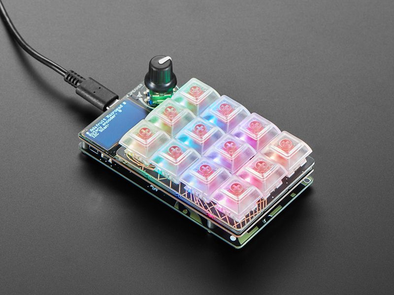
Strap yourself in, we’re launching in T-minus 10 seconds…Destination? A new Class M planet called MACROPAD! M here, stands for Microcontroller because this 3x4 keyboard controller features the newest technology from the Raspberry Pi sector: say hello to the RP2040. It’s speedy little microcontroller with lots of GPIO pins and a 64 times more RAM than the Apollo Guidance Computer. We added 8 MB of flash memory for plenty of storage.
Get ready to upgrade your desk’s mission control station with a CircuitPython or Arduino powered Macropad - complete with 12 buttons, OLED display, speaker and rotary encoder. Customize it for your spacecraft to help guide you through the great reaches of the unknown. (Or just have it type out your favorite emojis.)
Each of the 12 sockets can accept a Cherry MX-compatible key switch. No soldering required, just snap it in! Use any key switch you like - but we recommend ones with slots that will allow the matching twelve NeoPixels underneath to shine through.
This space-ship is also fitted with a 128x64 monochome OLED for a crisp heads-up display that can be used in Arduino or CircuitPython to display keymaps, stats, computer performance, etc. There’s also a rotary encoder with push-button soldered in. Twist and turn it or push to change volume or monitor brightness or scroll: whatever you like! A tiny speaker can give audio feedback or play fun bleepy tunes.
Want to add more hardware? No worries - a STEMMA QT port on the side lets you connect any I2C add-on peripherals from the massive STEMMA QT / Qwiic family of plug in boards.
Please note, the RP2040 chip does not currently have QMK support - this macropad is designed to be programmed in Arduino or CircuitPython! If QMK eventually does add RP2040 as a supported chipset (no ETA and no plans that we know of), we’ll update this page.
Technical details
- Raspberry Pi RP2040 Chip + 8MB Flash memory - Dual core Cortex M0+ at ~130MHz with 264KB or RAM. Runs CircuitPython, Arduino or MicroPython with ease and lots of space for development code and files
- USB C Connector for Power/Data - of course this can act as an HID device but also can be MIDI, UART, etc.
- 3x4 Mechanical key switch sockets - accepts any Cherry MX-compatible switches. Individually tied to GPIO pins (not matrix wired)
- One NeoPixel RGB LED per switch, on north side
- Rotary encoder, 20 detents per rotation, with push-switch on GPIO pin. Push switch is also used for entering bootloader mode when held down on power-up or reset.
- 128x64 SH1106 Monochrome OLED display - On high speed hardware SPI port for quick updates
- 8mm Speaker/Buzzer - With Class D amplifier and RC filter, can be used to make simple beeps and sounds effects.
- STEMMA QT Connector - Allows adding any I2C sensors/displays/devices with plug-and-play cables.
- Reset button - On the side, for quick restarting of code
- Four M3 mounting bosses - Make custom enclosures easily
Purchase
Contribute
Have some info to add for this board? Edit the source for this page here.
Adafruit Blinka Installation
We use a special library called adafruit_blinka (named after Blinka, the CircuitPython mascot) to provide the layer that translates the CircuitPython hardware API to whatever library the Linux board provides.
For example, on Raspberry Pi we use the python RPi.GPIO library. For any I2C interfacing we'll use ioctl messages to the /dev/i2c device. For SPI we'll use the spidev python library, etc. These details don't matter so much because they all happen underneath the adafruit_blinka layer.
Features: STEMMA QT/QWIIC, OSHWA Certified
Board Usage Options: Attached Device