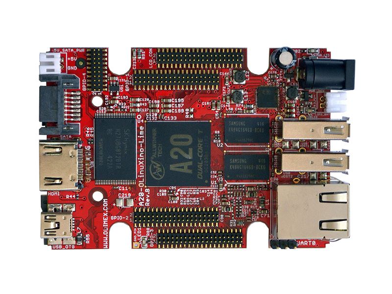
A20-OLinuXino-LIME2 by Olimex
A20-OLinuXino-LIME2 looks similar to both A20-OLinuXino-LIME and A10-OLinuXino-LIME. The major differences between A20-OLinuXino-LIME2 and A20-OLinuXino-LIME are:
- LIME2 has gigabit Ethernet (GbE), compared to the standard 100Mb Ethernet of the LIME
- LIME2 design provides double the RAM memory, compared to the LIME design (1024 vs 512)
- Much better routing of DDR3 memory.
- Increased the number of layers from 6 in LIME to 8 in LIME2
- Corrected pinout of the LCD and GPIO connectors (shields designed for the LIME layout are not compatible with the LIME2 layout)
The A10 and the A20 processors are pin-to-pin compatible. Because of the processor, software-wise the board is closer to A20-OLinuXino-LIME than to the A10-OLinuXino-LIME. This resemblance to other designs definitely might speed the development on the board - a lot of software written for A20-OLinuXino-LIME might work out-of-the-box with A20-OLinuXino-LIME2. Additionally, pinout tables, GPIO maps, etc released for A20-OLinuXino-LIME would apply to A20-OLinuXino-LIME2 (except for the 0.05” step connectors - LCD display and all the GPIOs connectors, which have a different layout compared to both A20-OLinuXino-LIME and A10-OLinuXino-LIME).
A20-OLinuXino-LIME2 features:
- A20 Cortex-A7 dual-core ARM Cortex-A7 CPU and dual-core Mali 400 GPU
- 1GB DDR3 RAM memory
- 1 gigabit native Ethernet
- optional 4GB NAND FLASH memory
- SATA connector with 5V SATA power jack
- HDMI FullHD 1080p
- 2x USB Low-Full-High-Speed hosts with power control and current limiter
- USB-OTG with power control and current limiter
- LiPo Battery connector with battery-charging capabilities
- LCD connector compatible with with 4.3”, 7.0”, 10.1” LCD modules from Olimex
- 160 GPIOs on three GPIO connectors
- MicroSD card connector
- DEBUG-UART connector for console debug with USB-SERIAL-CABLE-F
- status LED
- Battery charge status LED
- Power LED
- 2KB EEPROM for MAC address storage and more
- 2 BUTTONS with ANDROID functionality + RESET button
- 2 mount holes
- 5V input power supply, noise immune design
- PCB dimensions: 84 x 60 mm
Purchase
Contribute
Have some info to add for this board? Edit the source for this page here.
Adafruit Blinka Installation
We use a special library called adafruit_blinka (named after Blinka, the CircuitPython mascot) to provide the layer that translates the CircuitPython hardware API to whatever library the Linux board provides.
For example, on Raspberry Pi we use the python RPi.GPIO library. For any I2C interfacing we'll use ioctl messages to the /dev/i2c device. For SPI we'll use the spidev python library, etc. These details don't matter so much because they all happen underneath the adafruit_blinka layer.
Features: Ethernet, HDMI/DisplayPort, 40-pin GPIO, Infrared Receiver, OSHWA Certified
Board Usage Options: Linux Single Board Computer