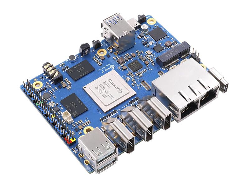
Orange Pi 5 Plus by Shenzhen Xunlong Software CO., Limited
Orange Pi 5 Plus uses Rockchip RK3588 8-core 64-bit processor, quad-core A76+quad-core A55, with 8nm process design, up to 2.4GHz main frequency, integrated ARM Mali-G610, built-in 3D GPU, compatible with OpenGL ES1.1/2.0/3.2, OpenCL 2.2 and Vulkan 1.2; embedded NPU supports INT4/INT8/INT16/FP16 mixed computing, with up to 6Tops of computing power, which can meet the edge computing needs of most end devices; 4GB/8GB/16GB LPDDR4/4X memory and eMMC socket, which can be connected with 16GB/32GB/64GB/128GB/256GB eMMC module. Orange Pi 5 Plus supports Orange Pi OS, the official operating system developed by Orange Pi, as well as Android 12, Debian 11, Ubuntu 22.04 and other operating systems.
Orange Pi 5 Plus provides abundant interfaces, including two HDMl output ports, one HDMl input port , two PCIe extended 2.5G Ethernet ports, an M.2 M-Key slot that supports installation of NVMe SSDs, and an M.2 E-Key slot that supports Wi-Fi6/BT modules. In addition, Orange Pi 5 Plus has two USB 3.0, two USB 2.0, and two Type-C (one of which is a power connector). Orange Pi 5 Plus has a wide range of uses to help embedded system development enthusiasts explore, and is also suitable for enterprises developing mini machine vision systems with multiple Ethernet ports, Orange Pi 5 Plus offers enhanced high-end applications performance experience to meet the needs of product customization in different industries.
Specifications
- Rockchip RK3588 (8nm LP process)
- 8-core 64-bit processor4 x Cortex-A76(2.4GHz), 4 x Cortex-A55(1.8GHz) and separate NEON co-processors
- Arm Mali-G610Built-in 3D GPUCompatible with OpenGL ES1.1/2.0/3.2, OpenCL 2.2 and Vulkan 1.2
- Embedded NPU supports INT4/INT8/INT16/FP16 mixed operation, with up to 6Tops computing power
- RK806-1
- 4GB/8GB/16GB (LPDDR4/4X)
- QSPI Nor FLASH: 16MB/32MBMicroSD card slot: up to 128GBeMMC socket: 16GB/32GB/64GB/128GB/256GB eMMC module can be attachedM.2 2280 slot for NVMe SSDs (PCIe 3.0 x4) up to 2,000 MB/s
- USB3.0 × 2 USB2.0 × 2 Type-C ×1
- 2x HDMI 2.1 out up to 8k@60FPS1x Type-C with DP TX 1.4A,up to 8K@30FPS1x HDMI in with up to 4K@60FPS1 x MIPI DSI TX 4 Lane,up to 4K @60Hz
- 1x 6Pin FPC socket
- 1XMIPI CSI 4 Lane
- CODEC:ES83881xAudio 3.5mm jack with mic1xMIC In1xHDMI 2.1 eARC1xSPK
- 2xPCIe 2.5G LAN(RTL8125BG)
- 40Pin dual row pins with the following multiplexing functions: UART, I2C, SPI, CAN, I2S, PDM, AUDDSM, SDIO, PWM, GPIO
- M.2 connector M key (bottom) for NVMe with PCIe 3.0 x4 lanes 2280 SSD
- M.2 connector E key (top) for connectivity with PCIe 2.0 x1/PCM/UART/USB2.0,2230 Wi-Fi6 /BT supported
- 1×MaskROM key 1xRecovery 1×on/off key
- Support Type-C power supply, 5V@4A
- 1x IR receiver tube
- RGB LED side light
- 5V FAN
- 2 Pin: RTC backup battery
- 3 Pin debug serial port (UART)
Purchase
Contribute
Have some info to add for this board? Edit the source for this page here.
Adafruit Blinka Installation
We use a special library called adafruit_blinka (named after Blinka, the CircuitPython mascot) to provide the layer that translates the CircuitPython hardware API to whatever library the Linux board provides.
For example, on Raspberry Pi we use the python RPi.GPIO library. For any I2C interfacing we'll use ioctl messages to the /dev/i2c device. For SPI we'll use the spidev python library, etc. These details don't matter so much because they all happen underneath the adafruit_blinka layer.
Features: Ethernet, USB 3.0, HDMI/DisplayPort, 40-pin GPIO, USB 3.0, NVME/M.2 Connector
Board Usage Options: Linux Single Board Computer