Pyboard by Damien George
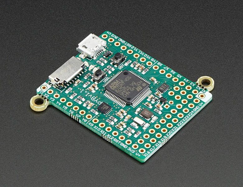
The pyboard is a compact and powerful electronics development board that runs MicroPython. It connects to your PC over USB, giving you a USB flash drive to save your Python scripts, and a serial Python prompt (a REPL) for instant programming. Requires a micro USB cable, and will work with Windows, Mac and Linux.
There are 3 main ways to control the pyboard:
- REPL: Connecting to your PC via USB, the board appears as a USB virtual comms port (CDC VCP) and you can use any serial program to connect and get a Python REPL prompt. This allows you to instantly type and execute Python commands, just like you would when running Python on your PC. You can also redirect the REPL to any of the UARTs on the pyboard.
- Remote script: You can change from REPL to raw REPL mode by sending ctrl-A, and then in raw REPL mode you can send an arbitrary Python script to the board for it to execute immediately. A Python script is available which makes using this mode very simple: you just run python pyboard.py script_to_run.py and this will execute script_to_run.py on the pyboard, returning any output.
- From file: The pyboard has a small, built-in filesystem which lives in part of the flash memory of the microcontroller. It also has an SD card slot if you want to extend the available storage. When you connect the pyboard to your PC, it appears as a USB flash storage device and you can access (mount) the internal filesystem and the SD card this way. If you copy a Python script to the filesystem and call it main.py then the board will execute this script when it starts up. This way you can run scripts without being connected to a PC.
Main features of the hardware:
- STM32F405RG microcontroller
- 168 MHz Cortex M4 CPU with hardware floating point
- 1024KiB flash ROM and 192KiB RAM
- Micro USB connector for power and serial communication
- Micro SD card slot, supporting standard and high capacity SD cards
- 3-axis accelerometer (MMA7660)
- Real time clock with optional battery backup
- 24 GPIO on left and right edges and 5 GPIO on bottom row, plus LED and switch GPIO available on bottom row
- 3x 12-bit analog to digital converters, available on 16 pins, 4 with analog ground shielding
- 2x 12-bit digital to analog (DAC) converters, available on pins X5 and X6
- 4 LEDs (red, green, yellow and blue)
- 1 reset and 1 user switch
- On-board 3.3V LDO voltage regulator, capable of supplying up to 300mA, input voltage range 3.6V to 10V
- DFU bootloader in ROM for easy upgrading of firmware
Purchase
Contribute
Have some info to add for this board? Edit the source for this page here.
Adafruit Blinka Installation
We use a special library called adafruit_blinka (named after Blinka, the CircuitPython mascot) to provide the layer that translates the CircuitPython hardware API to whatever library the Linux board provides.
For example, on Raspberry Pi we use the python RPi.GPIO library. For any I2C interfacing we'll use ioctl messages to the /dev/i2c device. For SPI we'll use the spidev python library, etc. These details don't matter so much because they all happen underneath the adafruit_blinka layer.
Board Usage Options: MicroPython Board