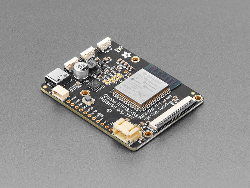
Qualia ESP32-S3 for TTL RGB-666 Displays by Adafruit
There’s a few things everyone loves: ice cream, kittens, and honkin’ large TFT screens. We’re no strangers to small TFT’s - from our itsy 1.14” color display that graces many-a-TFT-Feather to our fancy 3.5” 320x480 breakout screen. But most people who dabble or engineer with microcontrollers know that you sort of ‘top out’ at 320x480 - that’s the largest resolution you can use with every day SPI or 8-bit 8080 interfaces. After that, you’re in TTL-interface TFT land, where displays no longer have an internal memory buffer and instead the controller has to continuously write scanline data over a 16 or 18 or 24 pin interface.
RGB TTL interface TFT displays can get big: they start out at around 4.3” diagonal 480x272, and can get to 800x480, 800x600 or even 720x720. For displays that big, you need a lot of video RAM (800x480 at 24 bit color is just over 1MB), plenty of spare GPIO to dedicate, and a peripheral that will DMA the video RAM out to the display continuously. This is a setup familiar to people working with hefty microcontrollers or microcomputers, the sort of device that run cell phones, or your car’s GPS navigation screen. But until now, nearly impossible to use on low cost microcontrollers.
The ESP32-S3 is the first low-cost microcontroller that has a built in peripheral that can drive TTL displays, and can come with enough PSRAM to buffer those large images. For example, on the Adafruit Qualia ESP32-S3 for TTL RGB-666 Displays, we use a S3 module with 16 MB of Flash and 8 MB of octal PSRAM. Using the built in RGB display peripheral you can display graphics, images, animations or even video (cinepak, natch!) with near-instantaneous updates since the whole screen gets updated every ~30FPS.
This dev board is designed to make it easy for you to explore displays that use the “secondary standard’ 40-pin RGB-666 connector. This pin order is most commonly seen on square, round and bar displays. You’ll want to compare the display you’re using to this datasheet, if it matches you’ll probably be good! One nice thing about this connector ordering is that it also includes pins for capacitive touch overlay, and we wire those up to the ESP32-S3’s I2C port so you can also have touch control with your display.
Don’t forget! This is just the development board, a display is not included. Use any RGB-666 pinout display with or without a touch overlay. Note that you will need to program in the driver initialization code, dimensions, and pulse widths in your programming language. Here are some known-working displays that you can use in Arduino or CircuitPython:
- 2.1” 480x480 Round with Capacitive Touch
- 2.1” 480x480 Round without touch
- 4” 720x720 Square with Capacitive Touch
- 4” 720x720 Round without touch
- 4.6” 960x320 Rectangular Bar
On the Qualia board we have the S3 modules, with 16 pins connected to the TFT for 5-6-5 RGB color, plus HSync, VSync, Data Enable and Pixel Clock. There’s a constant current backlight control circuit using the TPS61169 which can get up to 30V forward voltage and can be configured for 25mA-200mA in 25mA increments (default is 25mA). Power and programming is provided over a USB C connector, wired to the S3’s native USB port. For debugging, the hardware UART TX pin is available as well.
Since almost every GPIO is used, and almost all RGB-666 displays need to be initialized over SPI, we put a PCA9554 I/O expander on the shared I2C bus. Arduino or CircuitPython can be instructed on how to use the expander to reset and init the display you have if necessary. The remaining expander pins are connected to two right-angle buttons, and the display backlight.
The expander is what lets us have a full 4-pin SPI port and two more analog GPIO pins - enough to wire up an MMC in 1-wire SDIO mode along with an I2S amplifier to make an A/V playback demo. Maybe we can even eat ice cream while watching kitten vids! There is also the shared I2C port, we provide a Stemma QT / Qwiic port for easy addition of any sensor or device you like.
Purchase:
Contribute
Have some info to add for this board? Edit the source for this page here.
CircuitPython 10.2.1
This is the latest stable release of CircuitPython that will work with the Qualia ESP32-S3 for TTL RGB-666 Displays. Use this release if you are new to CircuitPython.
Modules included in this download
_asyncio _bleio _bleio (native) _eve _pixelmap adafruit_bus_device adafruit_pixelbuf aesio alarm analogbufio analogio array atexit audiobusio audiocore audiomixer audiomp3 binascii bitbangio bitmapfilter bitmaptools board builtins builtins.pow3 busdisplay busio busio.SPI busio.UART canio codeop collections countio digitalio displayio dotclockframebuffer epaperdisplay errno espcamera espidf espnow espulp fontio fourwire framebufferio frequencyio getpass gifio hashlib i2cdisplaybus io ipaddress jpegio json keypad keypad.KeyMatrix keypad.Keys keypad.ShiftRegisterKeys keypad_demux keypad_demux.DemuxKeyMatrix locale lvfontio math max3421e mdns memorymap microcontroller msgpack neopixel_write nvm onewireio os os.getenv paralleldisplaybus ps2io pulseio pwmio qrio rainbowio random re rgbmatrix rotaryio rtc sdcardio sdioio select sharpdisplay socketpool socketpool.socketpool.AF_INET6 ssl storage struct supervisor supervisor.get_setting synthio sys terminalio tilepalettemapper time touchio traceback ulab usb usb_cdc usb_hid usb_midi vectorio warnings watchdog wifi zlibFeatures: External Display, Wi-Fi, Bluetooth/BTLE, STEMMA QT/QWIIC, USB-C, OSHWA Certified
CircuitPython 10.3.0-alpha.4
This is the latest development release of CircuitPython that will work with the Qualia ESP32-S3 for TTL RGB-666 Displays.
WARNING: On Espressif ESP32-S2 and ESP32-S3 boards with 4MB flash, CircuitPython 10.0.0-beta.0 and later require TinyUF2 bootloader version 0.33.0 or later. Older TinyUF2 bootloaders don't provide enough room for the firmware and cannot load it. See the Release Notes for more details, and see Update UF2 Bootloader below.
Alpha development releases are early releases. They are unfinished, are likely to have bugs, and the features they provide may change. Beta releases may have some bugs and unfinished features, but should be suitable for many uses. A Release Candidate (rc) release is considered done and will become the next stable release, assuming no further issues are found.
Please try alpha, beta, and rc releases if you are able. Your testing is invaluable: it helps us uncover and find issues quickly.
Release Notes for 10.3.0-alpha.4
Modules included in this download
_asyncio _bleio _bleio (native) _eve _pixelmap adafruit_bus_device adafruit_pixelbuf aesio alarm analogbufio analogio array atexit audiobusio audiocore audioi2sin audiomixer audiomp3 binascii bitbangio bitmapfilter bitmaptools board builtins builtins.pow3 busdisplay busio busio.SPI busio.UART canio codeop collections countio digitalio displayio dotclockframebuffer dualbank epaperdisplay errno espcamera espidf espnow espulp fontio fourwire framebufferio frequencyio getpass gifio hashlib i2cdisplaybus io ipaddress jpegio json keypad keypad.KeyMatrix keypad.Keys keypad.ShiftRegisterKeys keypad_demux keypad_demux.DemuxKeyMatrix locale lvfontio math max3421e mdns memorymap microcontroller msgpack neopixel_write nvm onewireio os os.getenv paralleldisplaybus ps2io pulseio pwmio qrio rainbowio random re rgbmatrix rotaryio rtc sdcardio sdioio select sharpdisplay socketpool socketpool.socketpool.AF_INET6 ssl storage struct supervisor supervisor.get_setting synthio sys terminalio tilepalettemapper time touchio traceback ulab usb usb_cdc usb_hid usb_midi vectorio warnings watchdog wifi zlibFeatures: External Display, Wi-Fi, Bluetooth/BTLE, STEMMA QT/QWIIC, USB-C, OSHWA Certified
Absolute Newest
Every time we commit new code to CircuitPython we automatically build binaries for each board and language. The binaries are stored on Amazon S3, organized by board, and then by language. These releases are even newer than the development release listed above. Try them if you want the absolute latest and are feeling daring or want to see if a problem has been fixed.
Previous Versions of CircuitPython
All previous releases of CircuitPython are available for download from Amazon S3 through the button below. For very old releases, look in the OLD/ folder for each board. Release notes for each release are available at GitHub button below.
Older releases are useful for testing if you something appears to be broken in a newer release but used to work, or if you have older code that depends on features only available in an older release. Otherwise we recommend using the latest stable release.
Install, Repair, or Update UF2 Bootloader
Latest version: 0.35.0
The UF2 bootloader allows you to load CircuitPython, MakeCode, and Arduino programs. The bootloader itself is not CircuitPython. On Espressif boards, the UF2 bootloader is called TinyUF2. If the TinyUF2 bootloader is installed, you can check its version by looking in the INFO_UF2.TXT file when the BOOT drive is visible (FTHRS2BOOT, MAGTAGBOOT, HOUSEBOOT, etc.)
In general, it is not necessary to update TinyUF2 at every version change. You can read the release notes on GitHub to see what has been changed. Update if you've been told about a necessary change or a bug fix.
Note: CircuitPython 10 and later, on Espressif boards with 4MB flash, requires TinyUF2 0.33.0 or later. The flash partition layout has changed (details).
If TinyUF2 has never been installed on the board, or it was removed by erasing or overwriting the flash, it must be installed in order to flash .uf2 files onto the board. But you don't need the TinyUF2 bootloader to upload .bin files. They can be uploaded using the built-in ROM bootloader, with the Adafruit WebSerial ESPTool or esptool.py.
Warning: Installing the TinyUF2 bootloader will erase everything that was previously on the board. Save any files in CIRCUITPY for which you don't have backups.
There are several ways to install the TinyUF2 bootloader on your board. Check to see if your board's manufacturer provides specific instructions. For Adafruit boards, consult the Factory Reset page in the Learn Guide for your particular board (example).
The easiest way to install TinyUF2 is to use the OPEN INSTALLER button (see above, in the CiruitPython sections). You can also use the Adafruit WebSerial ESPTool, or esptool.py, as described in the Factory Reset page.
- Plug board into a USB port on your computer using a data/sync cable. Make sure it is the only board plugged in, and that a charge-only cable is not being used.
- Press and hold the BOOT button (sometimes marked "B0").
- Press and release the RESET button (sometimes marked "RST").
- Release the BOOT button. This starts the ROM bootloader.
After installing TinyUF2, enter the UF2 bootloader by double-clicking the RESET button. On boards with an RGB status LED, you usually tap reset once, wait for the LED to turn purple, and tap again before the purple goes away. On other boards, consult the board documentation.
If you are updating TinyUF2, look at INFO_UF2.TXT to verify the new version of TinyUF2, by checking the version number. Then you will need to copy the CircuitPython.uf2 file to the BOOT drive.