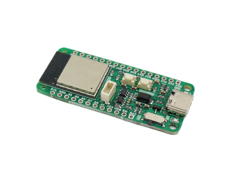
Pcbcupid GLYPH S3 by Pcbcupid
The Pcbcupid GLYPH S3 is a compact development board based on the ESP32-S3-MINI-1-N8 module, designed for AIoT, edge computing, and computer vision applications. With dual-core performance, wireless connectivity, and onboard LiPo charging, the GLYPH S3 delivers robust capabilities in a breadboard-friendly footprint.
The board features an onboard GLINK connector — QWIIC/STEMMA QT compatible — making it easy to connect hundreds of sensors and modules from Adafruit and SparkFun without soldering. It also includes auto power switching between USB and battery, battery capacity measurement via IO0, and a slide switch to cut battery power entirely.
The GLYPH S3 uses a built-in USB bootloader. To flash firmware, hold BOOT while plugging in USB — it appears as a COM port. Flash CircuitPython as a .bin using esptool.
For peripherals, the ESP32-S3 exposes two I2C controllers, three SPI controllers, and three UART controllers via the GPIO matrix — check the pinout for default assignments. All 20 GPIO pins support PWM with configurable frequency and duty cycle. The chip also includes vector extension instructions for lightweight on-device ML inference.
Board specifications
- ESP32-S3-MINI-1-N8 module
- Dual-core Xtensa LX7 processor up to 240 MHz, 3.3V logic
- 512KB SRAM, 8MB SPI flash (shared between code, files, and OTA)
- Wi-Fi 802.11 b/g/n (2.4 GHz) with BluFi, ESP-WIFI-MESH
- Bluetooth 5 LE with ESP-BLE-MESH support
- USB-C for power, programming, and serial debugging
- Built-in LiPo/Li-ion charger with charging status LED
- Auto power switching between USB and battery
- Reverse voltage protection
- Onboard slide switch to cut battery power
- Battery capacity measurement via IO0 (MSR pad)
- LiPo solder pads on rear of board
- 3.3V regulator, 900mA peak output
- 20 GPIO pins
- 9 × 12-bit ADC1 pins: IO1, IO2, IO4, IO5, IO6, IO7, IO8, IO9, IO10
- I2C: SDA=IO4, SCL=IO5 (second bus assignable to any GPIO pair)
- SPI: SCK=IO35, MOSI=IO36, MISO=IO37
-
UART0: TX=IO43, RX=IO44 UART1: TX=IO17, RX=IO18 - Onboard LED on GPIO21
- GLINK connector (QWIIC/STEMMA QT compatible)
- Dimensions: 50.8mm × 22.8mm × 1.6mm (without headers)
Learn More
Purchase
Contribute
Have some info to add for this board? Edit the source for this page here.
CircuitPython 10.3.0-alpha.3
This is the latest development release of CircuitPython that will work with the Pcbcupid GLYPH S3.
WARNING: On Espressif ESP32-S2 and ESP32-S3 boards with 4MB flash, CircuitPython 10.0.0-beta.0 and later require TinyUF2 bootloader version 0.33.0 or later. Older TinyUF2 bootloaders don't provide enough room for the firmware and cannot load it. See the Release Notes for more details, and see Update UF2 Bootloader below.
Alpha development releases are early releases. They are unfinished, are likely to have bugs, and the features they provide may change. Beta releases may have some bugs and unfinished features, but should be suitable for many uses. A Release Candidate (rc) release is considered done and will become the next stable release, assuming no further issues are found.
Please try alpha, beta, and rc releases if you are able. Your testing is invaluable: it helps us uncover and find issues quickly.
Release Notes for 10.3.0-alpha.3
Modules included in this download
_asyncio _bleio _bleio (native) _eve _pixelmap adafruit_bus_device adafruit_pixelbuf aesio alarm analogbufio analogio array atexit audiobusio audiocore audioi2sin audiomixer audiomp3 binascii bitbangio bitmapfilter bitmaptools board builtins builtins.pow3 busdisplay busio busio.SPI busio.UART canio codeop collections countio digitalio displayio dualbank epaperdisplay errno espidf espnow espulp fontio fourwire framebufferio frequencyio getpass gifio hashlib i2cdisplaybus io ipaddress jpegio json keypad keypad.KeyMatrix keypad.Keys keypad.ShiftRegisterKeys keypad_demux keypad_demux.DemuxKeyMatrix locale lvfontio math max3421e mdns memorymap microcontroller msgpack neopixel_write nvm onewireio os os.getenv paralleldisplaybus ps2io pulseio pwmio rainbowio random re rgbmatrix rotaryio rtc sdcardio sdioio select sharpdisplay socketpool socketpool.socketpool.AF_INET6 ssl storage struct supervisor supervisor.get_setting synthio sys terminalio tilepalettemapper time touchio traceback ulab usb usb_cdc usb_hid usb_midi vectorio warnings watchdog wifi zlibFeatures: Wi-Fi, Bluetooth/BTLE, USB-C, Battery Charging, Breadboard-Friendly
Absolute Newest
Every time we commit new code to CircuitPython we automatically build binaries for each board and language. The binaries are stored on Amazon S3, organized by board, and then by language. These releases are even newer than the development release listed above. Try them if you want the absolute latest and are feeling daring or want to see if a problem has been fixed.
Previous Versions of CircuitPython
All previous releases of CircuitPython are available for download from Amazon S3 through the button below. For very old releases, look in the OLD/ folder for each board. Release notes for each release are available at GitHub button below.
Older releases are useful for testing if you something appears to be broken in a newer release but used to work, or if you have older code that depends on features only available in an older release. Otherwise we recommend using the latest stable release.